This post is for Normand. I promised him that I would show this a long time ago.
In FreeCAD, you can create parametric objects with python scripting. What this means is you can create objects that change by altering their parameters. This makes it nice to create geometric objects similar to what you would find in the Draft workbench- rectangles, polygons, circles, and points are some of the parametric objects that Yorik has created. The Draft and Arch workbenches are pure python, so there are many examples of parametric objects to learn from.
A few months ago, I created a parametric milling machine vise, by importing *.step files from a well know vise manufacturer and worked them into some python scripting. When I first started playing with the script, I was copy/pasting it from my editor constantly, trying it out. This is fine for me to do, at first, when it was just one file to play with, but as the project got larger, it became a pain. I had added an *.svg file for the icon and split the *.step file in two. Things were starting to get a lot larger than my usual one page scripts, so it was time to make a small project out of it.
As the project got a little larger, I realized that this could be a pain for other folks to use, if I didn't clean it up and make it easy to install. I noticed that Yorik had made the dxf import/export part of his Draft workbench into an automatic download with FreeCAD, on the first instance of importing or exporting a DXF file. That looked like a good way to go for my script.
The small script that downloads the other files is here:
https://raw.githubusercontent.com/danielfalck/FCparametric/master/macros/vise_macro.py
Copy and paste it into your FreeCAD python console or into the FreeCAD macro editor and run it with the green play button.
The vise looks like this:
That last image shows the parameter for the jaw opening- it's in metric and you can give it value up to 220 mm and the movable jaw of the vise will open up.
Have fun with it.
Sunday, April 27, 2014
Sunday, January 19, 2014
Helping a Boy Scout
My son is in the Boy Scout program, here in the US. I feel that it is a very good program. He has learned some very good skills and had some awesome adventures. We also end up working together on a lot of projects. One of those was helping one of his fellow scouts with his Eagle project. This scout wanted to help a local charitable organization that gives clothes to needy children around the area. The organization didn't have any work tables for sorting clothes or benches for their clients to sit on, while they were waiting outside the door.
The scout working on this project knows that I like to design and build things, so he contacted me about the project. He started by getting the requirements from the charity director and came back with dimensions. We discussed some general design ideas and what materials he wanted to use. The materials would be construction grade timbers and plywood (laminated sheet).
I needed to make four different designs for these various tables and benches. There were three tables that needed to be different lengths and two benches that should be the same as each other. The tables were all very short, since they were going to be used for stacking boxes and clothes on. We wanted a similar design on all of them, since they were all going to the same place and it would make things easier for volunteers to assemble. After a group assembled one table, the next should be very familiar to them. We decided to make the benches look similar to the tables.
I decided to use a combination of FreeCAD for design and DraftSight for dimensioned drawings. I like using FreeCAD for design, because I am comfortable with it and feel that it is very powerful. I could start with one design and then change just a few parameters to make it fit the requirements for the next table or bench. I could probably even dimension all the drawings for the project in FreeCAD, but I am much more comfortable doing that in DraftSight.
Since we don't have an assembly workbench in FreeCAD yet- and I wanted all components to be related/driven by the table top, I did a sort of crude hack to keep everything in sync. I used PartDesign workbench with sketches and made a base sketch that represented the outside dimensions of the table or bench top for every set of components. The corners of the table top sketch were mirrored around X0 Y0 to give some consistency to my hack. I copied this same geometry from the table top sketch and pasted into one sketch and changed it into construction geometry
I copied and pasted this base construction geometry into four other sketches- to mimic the table top. Here is an example of the sketch construction:
(I am also working in inches on this project but chose not to change units in FreeCAD- so notice that the units in my sketch are in mm)
Within the sketches for everything, except the table top, I used additional construction geometry to space the padded part of the sketches away from the lip of the table top. This would typically be the over hang of the top and the thickness of the timber next to what I was working on:
One problem with this approach is that if I needed to change the length of the piece of furniture that I was working on, I had to change the construction geometry in several pieces to make this work. Since I didn't really care to code up a total parametric table in python, I thought that was a fair trade off. In the end, it wasn't a huge hassle to change the parameters for the 4 unique designs.
I did the components in groups:
1. table top -this was simple- make a sketch and pad it in a positive Z direction.
2. two long timbers for the frame - sketch their perimeters and pad in a negative Z direction.
3. two short cross timbers for frame - sketch their perimeters and pad in a negative Z direction.
4. all four legs - sketch their perimeters and pad in a negative Z direction.
5. two cross braces (mounted towards the floor on outside of legs) - move placement of the sketch to be lower than the table top and pad in a negative Z direction.
6. stretcher (mounted to the inside faces of the cross braces) - move placement of the sketch to be lower than the table top and pad in a negative Z direction.
7. The corner blocks were a little more difficult. They had to be sketched on a plane that was perpendicular to the table sketch. I ended up having to fudge on their locations a bit, but I survived :)
Here is a screenshot of all of the components put together:
In FreeCAD's Draft workbench there is a command to create a 2D projection of a 3D object called Shape2DView. I used that (with the help of a python script to speed up positioning) to create this:
These 2D views were then selected and exported as a *.DXF file for detailing in DraftSight.
We finished up construction earlier today, with the help of a lot of other scouts.
Saturday, November 30, 2013
Parsing Solid Models for Holes
I've been playing with a macro to get hole information (coordinates, diameter, etc) out of solid models in FreeCAD. It is a challenge and I don't think I will ever be totally done, because there are so many corner cases. I am concentrating on the types of parts that I would be milling in my shop- ie blocks of metal that I can drill with a simple 3 axis Bridgeport CNC mill. I will leave the 5 axis stuff to others :)
Here is a screenshot of what I have so far:
The lines coming up and out of the holes indicate that I am successful. Here is my macro:
FreeCADholefinder.py
The lines coming up and out of the holes indicate that I am successful. Here is my macro:
FreeCADholefinder.py
Sunday, October 27, 2013
Welcome to the Monkey Lab
I had a client request that I make an aluminum panel for mounting an LCD monitor and touchscreen for his research group. He supplied the monitor, touchscreen, a light, and a drink dispenser. Hmmm- sounds interesting. Who would be using the touch screen? Monkeys of course. Wow...
Here is how I did it: To begin with, I found spec sheets for the monitor and touch screen online.
Then I used HeeksCNC to create CNC code for milling out the panel.
Milling the whole thing on my Bridgeport CNC was a challenge. My Y axis travel was barely 10.75" and the cutout for the monitor/touchscreen was 10.3" alone. This meant that I needed to slide the ram that the milling head attaches to back and forth in Y to get the full range. To do that, I had to pick up on a known edge, with my edge finder, several times. That was a bit of a trick, but I got it to work.
Here is a picture of the finished assembly:
My client was very happy with the panel. Maybe I will make another and install it in my kitchen...
Sunday, July 21, 2013
Sunday, October 14, 2012
Heekscnc method of getting data to the python script
In my last post, I talked about how Heekscnc uses a master python script to coordinate the generation of g-code. In this post, I will try to convey how data is translated from the gui to this python script.
1. Look at the layout of HeeksCAD with the HeeksCNC installed :
Notice that there is an Objects tree on the left side. This is how all the data for the cnc program is graphically represented. Double clicking in items in this tree usually causes the parameters of that particular item to be displayed and editable.
To create a toolpath in Heeks, you need a 'sketch' (geometry), a 'tool' (end mill, drill, etc...) , and an 'operation' (profile, pocket, drilling...). So the first thing needed to get this ball rolling is the 'sketch'. Here I select the face of a solid and right click on it. A dialog pops up and allows me to create sketches from the face.
The representation of the 'sketch' (or two sketches in this one) appears in the 'Objects tree':
Notice that in my Objects tree there are already some tools listed. I have a tool table file stored on my hard drive with these tools in it.
I next select a sketch and one of the tools from the tree and then create an operation:
I selected a 'Profile' operation because I want to cut around the outside profile of this part.
I also did the same thing with the inner sketch, but this time used a smaller tool and then selected the 'Pocket' operation. In Heekscnc, the pocket operation dialog looks like this:
When I have a few operations set up, I usually get curious and want to see some results, so I usually post process what I have do far to see what the resulting tool paths look like:
Pressing the 'Post-Process' button causes the master python script to be built and placed in the 'Program' panel:
This is the same type of script that I blogged about last time. This script is run and creates a gcode file in the 'Output' panel.
So, there you have it- that is a basic rundown of how Heekscnc operates.
The thing that I want to stress in this post is that anything that is represented in the Objects tree will be translated to the master python script and later converted into gcode.
1. Look at the layout of HeeksCAD with the HeeksCNC installed :
Notice that there is an Objects tree on the left side. This is how all the data for the cnc program is graphically represented. Double clicking in items in this tree usually causes the parameters of that particular item to be displayed and editable.To create a toolpath in Heeks, you need a 'sketch' (geometry), a 'tool' (end mill, drill, etc...) , and an 'operation' (profile, pocket, drilling...). So the first thing needed to get this ball rolling is the 'sketch'. Here I select the face of a solid and right click on it. A dialog pops up and allows me to create sketches from the face.
The representation of the 'sketch' (or two sketches in this one) appears in the 'Objects tree':
I next select a sketch and one of the tools from the tree and then create an operation:
I selected a 'Profile' operation because I want to cut around the outside profile of this part.
I also did the same thing with the inner sketch, but this time used a smaller tool and then selected the 'Pocket' operation. In Heekscnc, the pocket operation dialog looks like this:
When I have a few operations set up, I usually get curious and want to see some results, so I usually post process what I have do far to see what the resulting tool paths look like:
Pressing the 'Post-Process' button causes the master python script to be built and placed in the 'Program' panel:
This is the same type of script that I blogged about last time. This script is run and creates a gcode file in the 'Output' panel.
So, there you have it- that is a basic rundown of how Heekscnc operates.
The thing that I want to stress in this post is that anything that is represented in the Objects tree will be translated to the master python script and later converted into gcode.
Friday, October 5, 2012
Python toolpath generation -HeeksCNC method
In this post, I want to explain the basics of how HeeksCNC uses python to generate toolpaths. The method that Dan Heeks came up with for doing this was brilliant. I have used bits and pieces of this method with different applications a lot and am just starting to use it with FreeCAD.
Here is a python script (Dan Heeks named it post.py in HeeksCNC) that is the main script for a gcode file.
post.py :
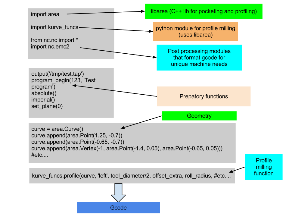
post.py reaches out to other scripts/modules in the heekscnc world for processing and formatting. These other scripts need to be in the python path, as you would expect.
libarea can be had from many places now, although I prefer to use the 'New BSD' licensed version that can be found here.
kurve_funcs.py is used for processing toolpaths for milling profiles. It depends on libarea too. I think we could probably untangle the dual dependency of calling 'import area' in post.py and in kurve_funcs.py, if we looked into it.
the line 'import nc.emc2' calls upon a user editable script that formats gcode for the emc2 (linuxcnc now) milling machine. There are a lot of other scripts in the nc directory that let one format the gcode for other machines.
Here is a summary of the components of this system again:
post.py :
import area
area.set_units(25.4)
import kurve_funcs
from nc.nc import *
import nc.emc2
output('/tmp/test.tap')
program_begin(123, 'Test program')
absolute()
imperial()
set_plane(0)
comment('Feeds and Speeds set for machining Please select a material to machine')
tool_defn( id=3, name='1/4 inch Carbide End Mill', radius=0.125, length=1.25, gradient=-0.1)
#(0.188 inch Carbide End Mill)
workplane(1)
comment('tool change to 1/4 inch Carbide End Mill')
tool_change( id=3)
spindle(7000)
feedrate_hv(33.07086614, 7)
flush_nc()
clearance = float(0.1968503937)
rapid_safety_space = float(0.07874015748)
start_depth = float(0)
step_down = float(0.035)
final_depth = float(-0.07)
tool_diameter = float(0.25)
cutting_edge_angle = float(0)
#absolute() mode
roll_radius = float(0.125)
offset_extra = 0
comment('Sketch')
curve = area.Curve()
curve.append(area.Point(1.25, -0.7))
curve.append(area.Point(-0.65, -0.7))
curve.append(area.Vertex(-1, area.Point(-1.4, 0.05), area.Point(-0.65, 0.05)))
curve.append(area.Point(-1.4, 0.45))
curve.append(area.Vertex(-1, area.Point(-0.65, 1.2), area.Point(-0.65, 0.45)))
curve.append(area.Point(1.25, 1.2))
curve.append(area.Vertex(-1, area.Point(2, 0.45), area.Point(1.25, 0.45)))
curve.append(area.Point(2, 0.05))
curve.append(area.Vertex(-1, area.Point(1.25, -0.7), area.Point(1.25, 0.05)))
roll_on = 'auto'
roll_off = 'auto'
extend_at_start= 0
extend_at_end= 0
lead_in_line_len= 0.25
lead_out_line_len= 0
kurve_funcs.profile(curve, 'left', tool_diameter/2, offset_extra, roll_radius, roll_on, roll_off, rapid_safety_space, clearance, start_depth, step_down, final_depth,extend_at_start,extend_at_end,lead_in_line_len,lead_out_line_len )
absolute()
program_end()
This script is processed like this:post.py reaches out to other scripts/modules in the heekscnc world for processing and formatting. These other scripts need to be in the python path, as you would expect.
libarea can be had from many places now, although I prefer to use the 'New BSD' licensed version that can be found here.
kurve_funcs.py is used for processing toolpaths for milling profiles. It depends on libarea too. I think we could probably untangle the dual dependency of calling 'import area' in post.py and in kurve_funcs.py, if we looked into it.
the line 'import nc.emc2' calls upon a user editable script that formats gcode for the emc2 (linuxcnc now) milling machine. There are a lot of other scripts in the nc directory that let one format the gcode for other machines.
Here is a summary of the components of this system again:
Sunday, September 30, 2012
Our book on FreeCAD has been published
Brad and I have been working on a small book on FreeCAD for Packt Publishing, since February of this year. It has now been published and can be purchased through Packt and Amazon. It was an interesting experience writing the book. I think we initially wrote the whole thing in the span of two weeks and spent the remainder of our time until August editing it. I think we learned a lot about writing and a lot about FreeCAD itself.
Friday, June 8, 2012
Experimental Online APT360 Processor
Edit-I have disabled the server for this, since I needed it for something else. This doesn't work anymore.
I have been playing with websockets and a Linode server. A friend of mine, Brent Muller, set up APT360 on the linode server and I created a python-tornado websocket interface to it.
Paste Apt code in the top text box and press the Post Code button. If there are no errors (be careful to make sure the first line of code begins on column one and that there is a line after 'fini') you should get gcode in the bottom pane. For those of you who know what APT360 is, have fun.
Available Post Processors: a1100m, cent1, cent2, dmb, dmb2, e4axvt, e5axtr, e5axvt, emc, webgl2
Sunday, May 13, 2012
Javascript post processing
This is a test to see how javascript could work for post processing. In the left textarea, add terms like 'g0(0,0,0)' for rapid moves, 'g1(1,0,0)' for feed moves and then press the 'Post' button to get some GCode in the right textarea box. Some of you might wonder why? This is just a test for something bigger.
GCode Post Processor
g0(x,y,z) - rapid
g1(x,y,z) - feed move
g2(x,y,i,j) - clockwise arc - i,js in absolute coordinates
g3(x,y,i,j) - counter clockwise arc
feedrate = 33.0 - feedrate
JavaScript Post Processor
Saturday, May 12, 2012
Javascript blogger test
This free script provided by
JavaScript
Kit
Sunday, April 15, 2012
Cloud CADCAM via twisted python
I have been working a bit with Julian Todd of FreeSteel . We have started working on a way of serving out toolpaths, using his 'Slicer' routine from a server. The server takes triangle vertices in and returns tool location paths, for waterline type machining. Julian is very familiar with twisted python and plans on using it for his own server. At the moment, I am running his library locally.
Here is an image of a part that I designed in FreeCAD and applied this 'Slicer' scheme to:

The python code that I used for this doesn't post process into actual g-code, but it could.
import Mesh
import Part,FreeCAD
from FreeCAD import Base,Vector
import freesteelpy as kernel
s=Gui.Selection.getSelectionEx()
s1 = s[0]
m1 = s1.Object
m1.Mesh.write("/home/danfalck/mesh1.py") #write the triangle list to a file
f1 = m1.Mesh.Facets #returns out a list of facets
fssurf = kernel.FsSurf.New()
for f in f1:
fssurf.PushTriangle(f.Points[0][0],f.Points[0][1],f.Points[0][2], f.Points[1][0],f.Points[1][1],f.Points[1][2], \
f.Points[2][0],f.Points[2][1],f.Points[2][2])
def doit(fssurf, z , rad):
fssurf.Build(1.0)
fshoriztoolsurf = kernel.FsHorizontalToolSurface.New()
fshoriztoolsurf.AddSurf(fssurf)
fshoriztoolsurf.AddCylinder(rad, z, 10.0, 0) #cylinder radius, lower Z, upper Z, how the cylinder is connected to the rest of the tool -tangential etc.
fsimplicitarea = kernel.FsImplicitArea.New(0)
fsimplicitarea.AddHorizToolSurf(fshoriztoolsurf)
fsimplicitarea.SetContourConditions(0.99, -1.0, 0.002, 2, -1.0, 0.9)
fsweave = kernel.FsWeave.New()
fsweave.SetShape(-25, 25, -25, 25,.1) #(-x, -y, x , y of bounding area, last arg is granularity of path)
fsimplicitarea.GenWeaveZProfile(fsweave)
fsweave.GetNContours()
fspath2x = kernel.FsPath2X.New(0)
fspath2x.RecordContour(fsweave, False, 0, 0.0)
fspath2x.GetNpts()
[ (fspath2x.GetD(i,0), fspath2x.GetD(i,1)) for i in range(fspath2x.GetNpts()) ]
[ (fspath2x.GetD(i,0), fspath2x.GetD(i,1), fspath2x.GetD(i,2)) for i in range(fspath2x.GetNpts()) ]
pt0 = (fspath2x.GetD(0,0), fspath2x.GetD(0,1), fspath2x.GetD(0,2))
#FreeCAD.ActiveDocument.addObject("Part::Feature","rapids)\n")
c = Part.Compound([])
for i in range(fspath2x.GetNpts()-1):
line = ( Part.makeLine( (fspath2x.GetD(i,0), fspath2x.GetD(i,1), fspath2x.GetD(i,2) ) , ( fspath2x.GetD(i+1,0), fspath2x.GetD(i+1,1), fspath2x.GetD(i+1,2) ) ) )
c.add(line)
c.Placement=Base.Placement(Base.Vector(0.00,0.00,z),Base.Rotation(0.00,0.00,0.00,1.00))
Part.show(c)
rad = 1.0
startdepth = 2.5
zdepth = -3.0
stepdown = .25
steps = startdepth
while startdepth >= zdepth:
z = startdepth
doit(fssurf,z,rad)
startdepth =startdepth-stepdown
Sorry for the poor formatting of the source code- I need to figure that out soon.
Friday, January 13, 2012
Sunday, January 1, 2012
More Progress
Saturday, December 31, 2011
Using QtDesigner!!!!
A little progress report
I'm still learning the internals of FreeCAD. I helped the main project a little by creating a lowly 'Point' class, which Yorik integrated into the Draft workbench. Doing this helped me get familiar with the source. Having this object class will also be useful later on for CAM work (start and end points for profiles etc).
I have also made some scripts for extracting libarea 'curve' elements from objects in the FreeCAD document. Right now, I can click on edges of solids or lines and arcs in Sketches or Draft elements and then run a macro to produce some python code that can be pasted into a HeeksCNC python script for producing g-code.
The resulting code looks like this:
curve = area.Curve()
#open path
curve.append(area.Point(62.244881,-33.935955))
curve.append(area.Vertex(-1 , area.Point( 57.129109, -39.051727), area.Point(57.129109, -33.935955)))
curve.append(area.Point( -56.043546, -39.051727))
curve.append(area.Vertex(-1 , area.Point( -64.821892, -30.273381), area.Point(-56.043546, -30.273381)))
If you've ever used HeeksCNC, this code should look familiar.
I can take this code and paste it into a script such as this one:
import sys
sys.path.insert(0,'/usr/lib/heekscnc/')
import math
import area
area.set_units(1)
import kurve_funcs
from nc.nc import *
import nc.emc2b
output('/home/danfalck/Documents/freecad/curve_output/test.tap')
program_begin(123, 'Test program')
absolute()
metric()
flush_nc()
set_plane(0)
workplane(1)
#(4.7752 mm Carbide End Mill)
tool_defn( id=4, name='4.7752 mm Carbide End Mill', radius=2.3876, length=23.876, gradient=-0.1)
tool_diameter = float(4.7752)
cutting_edge_angle = float(0)
#path/geometry section
curve = area.Curve()
curve.append(area.Point(62.244881,-33.935955))
curve.append(area.Vertex(-1 , area.Point( 57.129109, -39.051727), area.Point(57.129109, -33.935955)))
curve.append(area.Point( -56.043546, -39.051727))
curve.append(area.Vertex(-1 , area.Point( -64.821892, -30.273381), area.Point(-56.043546, -30.273381)))
#end of path/geometry section
#program action:
comment('tool change to 4.7752 mm Carbide End Mill')
tool_change( id=4)
spindle(7000)
feedrate_hv(840, 100)
clearance = float(5)
rapid_safety_space = float(2)
start_depth = float(0)
step_down = float(2)
final_depth = float(-10)
roll_radius = float(5.0)
offset_extra = 0
roll_on = 'auto'
roll_off = 'auto'
extend_at_start= 0
extend_at_end= 0
lead_in_line_len= 5.0
lead_out_line_len= 5.0
kurve_funcs.profile(curve, 'left', tool_diameter/2, offset_extra, roll_radius, roll_on, roll_off, rapid_safety_space, clearance, start_depth, step_down, final_depth,extend_at_start,extend_at_end,lead_in_line_len,lead_out_line_len )
absolute()
program_end()
The resulting gcode might give something like this (backplotted in FreeCAD):
Saturday, November 5, 2011
FreeCAD
Lately I've gotten interested in FreeCAD .
FreeCAD is "a a general purpose Open Source 3D CAD/MCAD/CAx/CAE/PLM modeler" written in C++, with python scripting built in. It runs on Windows, Linux, and supposedly Mac OS X. FreeCAD is built "with a modular software architecture which makes it easy to provide additional functionality without modifying the core system."
I am interested in adapting some of the HeeksCNC libraries to a plugin for FreeCAD. My motives are practical, I think:
1. FreeCAD's is maintained by a core group of developers already. They are very active.
2. It has python scripting built in by default. HeeksPython is great,but is broken frequently by changes to HeeksCAD itself.
3. The OS related build system is already taken care of for all desktop platforms. I don't want to deal with this at all.
4. There is an active FreeCAD forum.
5. I just want to work on CADCAM and import/export issues.
I have been working on improving the DXF import/export scripts that are already in FreeCAD and have started on a DXF to constraints/Sketcher importer. I have also started work on backplotting CNC g-code into FreeCAD:

The screenshot is from some g-code that I generated in HeeksCNC and backplotted using the HeeksCNC python scripting, adapted to FreeCAD.
Saturday, August 27, 2011
Waterline Machining
I have been machining a part that has a draft angle of 20 degrees on two walls and I think I found a good method.
Here is a screenshot of one version of the part, where I tried using 'zigzag' machining with Heekscnc:
When I actually did machine the part, it took about an hour and 20 minutes. I knew that I would have to set my boundaries closer to the tapered walls, if I wanted to save any time on the next part. Also notice the extra tool paths that are cutting air. I wanted to eliminate them.
Heekscnc uses 3D machining methods from Opencamlib http://code.google.com/p/opencamlib/ . There are several strategies for 3D milling there and 'waterline' is one of them. Waterline machining makes the tool path run at a constant Z level around the part. This seemed like a perfect strategy for the part I was working on. I tried out the HeeksCNC implementation of ocl waterline using a flat bottomed end mill and got a tool path that looked like this:
I liked the approach, but I only wanted to machine the tapered walls of the part. There were some entries in the Heekscnc waterline operation for boundaries, but they weren't functioning. I looked at the source code and added some logic to 'ocl_funcs.py' to connect them and was then able to get the tool path to look like this:
Ahh! That's much better. When I actually milled the part, my cycle time was down to 20 minutes.
Sunday, July 10, 2011
Translating toolpaths with scriptop
I have committed a change to my git repo that lets me snap new coordinates anywhere on the drawing and then have my toolpaths generated relative to it. This becomes useful if I import a dxf file and the geometry isn't anywhere near where it needs to be for sensible fixture offsets. Here's an example:

Notice how the origin/datum is to the far left of the rectangular sketch. To make things a little easier, create a new coordinate system with 'Set Origin' (I like to use the 'Pick 1 Point' option).

Snap the new coordinate datum to the upper left corner of the sketch:

Create a 'ScriptOp' operation and copy/paste the new coordinate object into it. Then you can position the ScriptOp operation just before a regular machining operation,such as Profiling. When you post process, the gcode will be shifted by the distance that the new coordinate object is away from the original origin:

This is useful if you want to place your fixture offset in a familiar place. In the case of this sketch, the fixture offset (G54-G59) is placed in the upper left corner. I like to place a fixture offset on that corner because I touch off to the fixed back jaw of my vise and the left side of the part. There are always other ways of doing things, but that is a common one.
Note for my fellow git brothers: I changed nc.py, iso.py, and ScriptOp.cpp to make this happen :)
Saturday, July 9, 2011
Manual Tool Changer Carousel
My Bridgeport CNC mill uses 'Quick Switch 30' tooling. I like it for prototype work- it's easy to change out a tool by hand. All that's required is a spanner wrench at the spindle nose to loosen and tighten the knurled ring. It only takes a quarter turn to secure the tool in the taper. When I bought the mill, it came with a small aluminum plate that had 5 holes in it for holding tools, that could be clamped down to the table. This made it convenient to have 5 tools within reach while running programs. This is not enough for the programs that I am running nowadays. Right now, I have 29 Quick Switch 30 toolholders and I like to use the hell out of them during a program. Sometimes I have 8 different tools in a program.
I have been thinking about using an old Heathkit turntable platter that I have had in my stock pile (junk pile) for many years- to make a tool carousel. It's a substantial aluminum casting that's .20" thick in it's cross section and about 11" diameter. It looked like I could put 10 holes in it that would comfortably hold 10 QC 30 tools.
I ended up writing a program in HeeksCNC, using scriptop to bore holes with an end mill. It ended up being pretty slick- it descends in a helical motion and then spirals out with an even chip load on the tool. It was kind of fun to write and use.


Here's a link to my 'array_of_holes.heeks' file that was used for this project:
https://github.com/danielfalck/heekscnc/blob/master/contrib/scriptop/array_of_holes.heeks
Subscribe to:
Posts (Atom)


.png)