Sunday, May 22, 2011

Cutter Radius Compensation

I do a lot of milling in my home shop with my CNC Bridgeport mill. This machine has a Centroid M40 control on it that works pretty well. It has a feature called 'cutter radius compensation' in it that is standard on most modern controls. This allows for variations in cutter size or cutting conditions such that the machine operator (me) can make the toolpath run closer or further from the part profile. Cutter radius compensation is a subject that is covered pretty well in cnc programming textbooks, so I won't get into it much here, except to mention a few things about programming to 'part profile' or programming to 'cutter centerline'. Over 20 years ago, I was taught to program a part to 'part profile' like this, when using cutter radius comp:


Using this method, it's easy to look at a blueprint and just write the program by hand. You can just enter the end points and center points of lines and radius' and add a G41 (or G42) to your code. Once the program is done,it's pretty intuitive to change the diameter value in the control to the actual diameter of the cutter and get a reasonable part milled. If your end mill is .499 inches in diameter, just enter that as the D value in your control. If you want to make the part a bit bigger all around, enter the value as .501 and 'trick' the control into moving the path away from the part profile. With just a little simple math, done in your head, it's easy to manipulate the size of the part.

After moving across the country, to the west coast, I was taught a different way of using cutter radius compensation. A part programmer can use a CAM system to make the cutter path the radius value of the cutter away from the part profile and then use very small values in the D value of the control to manipulate the size of the part.


The cutter value can be .000" to be 'on the line' and you can change it by .001" or -.001" to manipulate the part profile.
I guess you could call this the 'West Coast' method. Nowadays, I am using this method with my home shop mill. I've just gotten used to it. I'm using my Centroid post processor with HeeksCNC and things work well for this. In the post, there is a bit of code that adds a lead in line to the roll on radius. This is needed to give the control a bit of distance to move the cutter before it reaches an arc, while doing the cutter compensation. If I don't have a straight line on the first line of a crc move, the control gives an error. It works the same way on the lead out line just after the roll off radius. I don't think EMC2 works this way- I think you can start with a roll on radius with a crc command, without getting an error. This seems to be an exception in the cnc control world though. Most commercial controls expect a straight line.

Friday, November 5, 2010

Creating Cross Sections of Parts in HeeksPython

Ok, I worked out a scheme for creating a cross sectional view of a simple assembly in HeeksPython. I altered my dxf_to_heekspython script slightly to let the sketches have unique IDs. Then it's possible to create objects out of them and do CSG operations to the unique objects.
Here is a sample script:

import HeeksPython as cad
import sys
sys.path.insert(0,'/home/dan/heeks/heekspython2/examples')
import dxf_to_heekspython
from math import pi

a1 = 90*(pi/180)


units = 25.4 #inch units
cad.setcolor(255,255,255)
r1='/home/dan/Documents/drawings/revolve1.dxf'
part1 = "cad.setcolor(0,0,0)\n"
part1 = dxf_to_heekspython.gen_heekspython_entities(r1,1)
part1 = part1 +"cad.scale(sketch1,0,0,0,units)\n"
part1 = part1 +"cad.setcolor(255,255,255)\n"
part1 = part1 +"cad.revolve(sketch1,360)\n"
part1 = part1 +"cup = cad.getlastobj()\n"
exec(part1)
cad.setcolor(0,255,0)
r2='/home/dan/Documents/drawings/revolve2.dxf'
part2 = "cad.setcolor(0,0,0)\n"
part2 = dxf_to_heekspython.gen_heekspython_entities(r2,2)
part2 = part2 +"cad.scale(sketch2,0,0,0,units)\n"
part2 = part2 +"cad.setcolor(0,255,0)\n"
part2 = part2 +"cad.revolve(sketch2,360)\n"
part2 = part2 +"sleeve = cad.getlastobj()\n"
exec(part2)

cad.view_extents()

c1= '/home/dan/Documents/drawings/cutaway.dxf'
cut = dxf_to_heekspython.gen_heekspython_entities(c1,3)
cut = cut + "cad.scale(sketch3,0,0,0,units)\n"
cut = cut + "cad.revolve(sketch3,90)\n"
cut = cut + "cutter = cad.getlastobj()\n"
cut = cut + "cad.rotate(cutter,0,0,0,1,0,0,a1)"
exec(cut)

cad.cut(cup,cutter)
cad.cut(sleeve,cutter)

Here is the assembly:


Just prior to importing these dxf files into HeeksPython I had also added fillets to all the corners in Caduntu (yes, this works well now Ries!). So now I can work in my favorite 2D CAD program and my favorite 3D CADCAM program to create assemblies with python.


It's easy to alter the design of the parts in this assembly by simply changing them in the dxf files:


Then re run the python script in HeeksPython:


One major improvement that I would like to do is to make the dxf_to_heekspython script deal with layers. Then I could do all the dxf editing in one file in Caduntu.
As I learn more about C++ programming, I might be able to utilize the functions in dxf.cpp from HeeksCAD itself. Importing would run much faster and I could take advantage of the things that already work well, like layers and importing polylines (which isn't currently implemented in the python script).

More DXF to HeeksPython Experiments

I created a python script to import a dxf file into HeeksPython, using parts of Doug Blanding's excellent python program 'Cadvas'. Doug and I have emailed back and forth over the years and he is happy to see his creation used for different things. He's not supporting it anymore, but in it's present state, it's a very good program to study. It's very simple and well laid out.
Included with Cadvas is the dxf.py module. I have copied some of it and altered it to suite my needs for dxf to heekspython conversion and uploaded the script into the /examples directory in the HeeksPython project. This script is called dxf_to_heekspython.py. Here are two profiles created in Qcad, that I want to manipulate in HeeksPython:


Here is a script to bring them into HeeksPython as separate revolved solid parts:

import HeeksPython as cad
import sys
sys.path.insert(0,'/home/dan/heeks/heekspython2/examples')
import dxf_to_heekspython


units = 25.4 #inch units
cad.setcolor(255,255,255)
r1='/home/dan/Documents/drawings/revolve1.dxf'
part1 = "cad.setcolor(0,0,0)\n"
part1 = dxf_to_heekspython.gen_heekspython_entities(r1)
part1 = part1 +"cad.scale(sketch,0,0,0,units)\n"
part1 = part1 +"cad.setcolor(255,255,255)\n"
part1 = part1 +"cad.revolve(sketch,360)"
exec(part1)
cad.setcolor(0,255,0)
r2='/home/dan/Documents/drawings/revolve2.dxf'
part2 = "cad.setcolor(0,0,0)\n"
part2 = dxf_to_heekspython.gen_heekspython_entities(r2)
part2 = part2 +"cad.scale(sketch,0,0,0,units)\n"
part2 = part2 +"cad.setcolor(0,255,0)\n"
part2 = part2 +"cad.revolve(sketch,360)\n"
part2 = part2 +"p1 = cad.getlastobj()\n"
exec(part2)

cad.view_extents()

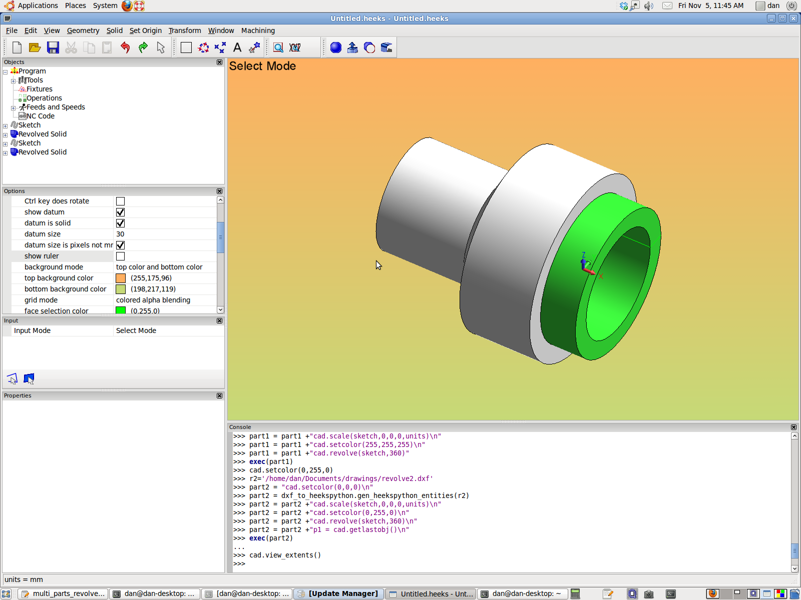
Here is a screenshot of the resulting parts generated with this script:


The advantage of using this dxf_to_heekspython is that the dxf entities can be manipulated/transformed as they are brought in. I have some things that I would like to do with some dxf files - create solids by revolving them around the X axis. Eventually I will create cutaway views using this technique.

Friday, October 29, 2010

Well, it's been quite a long since I posted anything (obviously). I've been busy trying to learn a bit of C++ coding, in my quest to learn the ins and outs of HeeksCAD,HeeksCNC, and HeeksPython.
I am mostly doing the 'learn by example' route, plus a few good tutorials, books, and some very helpful advice from Dan Heeks himself. If I get into a bind, he usually can point to some example code that helps me understand things.
I have been able to add quite a few new functions to HeeksPython and a few things to HeeksCAD itself. HeeksPython is fun to add functions to, because there is a lot of 'low hanging fruit' so to speak. It's pretty easy to add a python binding to HeeksCAD, if there is already a C++ function in /interface/HeeksCADInterface.cpp . I started out by copying jonpry's existing functions ('NewArc', 'NewLine' etc). As I have gotten a little more experience, I have gotten more adventurous and added functions for deriving point data from the GraphicsCanvas itself. I also found a way of adding fillets to pairs of 2D lines. Over the last month, I have added ways of creating a new coordinate system,returning the parameters of coordinate systems,text,and a way of importing dxf files from python.
The HeeksPython function 'importdxf' is exiting for me because I have plans for creating solids quickly with the aid of other 2D cad programs like caduntu , qcad, or even true-type-tracer-dxf. Having HeeksPython loaded with functionality will help automate the design process somewhat.
Here is an example of a script that uses true-type-tracer-dxf to create some text on the HeeksCAD graphics screen:

import os
import HeeksPython as cad

path = '''/home/dan/Documents/drawings/ttt/'''
program = '''truetype-tracer-dxf'''
phrase = ''' \' this is a test \' '''
pipe = ''' > '''
file = '''aphrase.dxf'''

out = program + phrase + pipe + path + file
os.system(out)

f = path + file

cad.importdxf(f)
cad.view_extents()

Sunday, July 4, 2010

HeeksCNC + python == APT360

One of my favorite CNC programming languages is APT360. It's a totally parametric way of creating gcode for cnc machines. It's also not very user friendly, if you don't use it all the time and get rusty, like I do. I'm a big fan of parametric programming and also a big fan of the python programming language. It's fairly easy for a non programming like me to get into and it's very popular, so there are many resources on the web for it.
In one of my previous blog entries, I mentioned that HeeksCNC uses python as the underlying scripting between the main C++ code and the post processed g-code. This week, Dan Heeks introduced a blank scipting object in HeeksCNC that lets the user create scripts in python and retain them in the order wanted in the HeeksCAD file. 'New Script Operation', as it's named in the HeeksCNC machining menu let's you do anything that you can think of in python and insert it into the Heeks python output.
As soon as I got my hands on the source code and compiled it, I started playing with parametric holes and helix operations.


Here is a small and very limited script for creating a helix in gcode:

def helix(x_cen,y_cen,z_depth,dia,pitch,z_clear):
    r=dia/2
    flush_nc()
    rapid(x=x_cen,y=y_cen)
    rapid(z=z_clear)
    feed(z=z_depth)
    feed(x=(x_cen+r))

    while (z_depth < z_clear):

        arc_ccw(x=(x_cen-r),y=y_cen,z=(z_depth+pitch*.5),i=-r,j=0)

        arc_ccw(x=(x_cen+r),y=y_cen,z=(z_depth+pitch),i=r,j=0)
        z_depth= z_depth+pitch
    feed(x=(x_cen))

d=.25
p=.125
zclr=.1
zdepth=-1.0
helix(.5,.5,zdepth,d,p,zclr)
helix(5.5,.5,zdepth,d,p,zclr)
helix(5.5,3.5,zdepth,d,p,zclr)
helix(.5,3.5,zdepth,d,p,zclr)

This snippet of code doesn't take into account anything having to do with tool radius/diameter.

Here you can see that I mixed script ops and a regular profile machining op:


Fun stuff!

Sunday, June 20, 2010

Drag and Drop in HeeksCAD

Yesterday, several of us were chatting with Dan Heeks on #cam in irc and someone asked him if he could add 'drag and drop' capabilities to HeeksCAD. This would make it much easier to put objects and operations in order for machining.
Dan went ahead and programmed this up today and it is great.
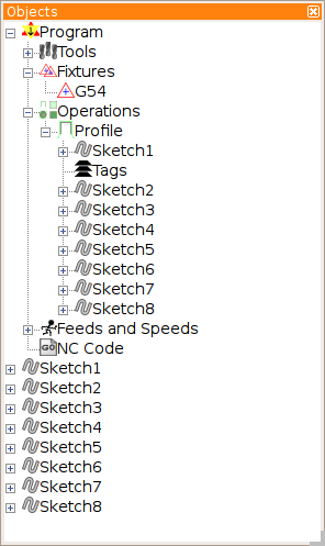
Now it is very easy to create sketches, copy them, and then paste them into different machining operations- and then put them in a logical machining order. It is also much easier to re-order sketches to one's own liking.


Now, it is very easy to reorder the sketches in the 'Objects' panel any way that you want.


Here's what I tried and was very pleased with:

I created a profile operation with one of the sketches.


I then copied all the other sketches and did a 'paste into' the profile operation


The order that the paths are machined isn't exactly optimized:


So then I dragged the sketches into the right order, inside the profile operation:


Here is what the paths look like now:


Similarly, you can do the same thing with machining operations like profile,pocket,drill,etc.

Saturday, June 5, 2010

Programming a Scanned Logo

I am doing a job for a guy who sent me a scanned bitmap of his logo. He wants this logo engraved on a brass guitar tailpiece.


I wanted to try out Inkscape to make an SVG file that I could import into HeeksCNC for generating Gcode. Inkscape has a 'trace bitmap' function under the 'Path' menu that should do the job. There are also some nice CNC gcode generating plugins for Inkscape that will make code directly out of the application. I prefer to use HeeksCNC for generating the code, because I have a good post processor for my Centroid controlled mill that lets me generate code without having to do any editing to it. I also need to combine some CAD data that don't trust to Inkscape with the logo, that's going to need to be engraved too.

The first thing that I did with that scanned image was open it in Gimp and crop it:


Then I imported it into Inkscape, made sure that it was still selected then did this:
1. In the top menu select 'Path'
2. select 'Trace Bitmap'

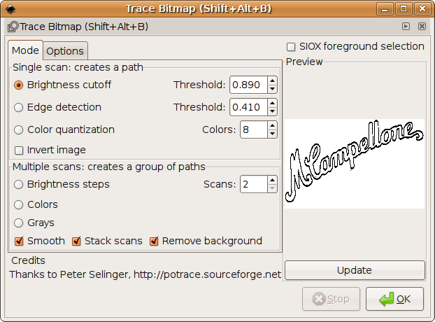
Here is the dialogue box that pops up (after I selected 'Brightness Cutoff' and 'Update'):


Once you hit 'OK' in that box, the converted vector path is hiding behind the original bitmap. I always slid it out from under the bitmap to look at it because I intended on copying and pasting the path into something else later.


If you copy and paste the vectorized path into a new Inkscape file, it can be saved as a new *.svg that Heekscad can import.


This looked pretty nice, but there was a problem- there were two paths all the way around the logo. I just want one nice clean path to engrave. Hmmm... it seems that the bitmap tracing looks at both edges of the black lines in the scan. I had played with 'Brightness Cutoff' and 'Edge detection' in the bitmap trace dialogue in Inkscape. 'Brightness Cutoff' seemed to give better results initially.
I opened up the bitmap in Gimp again and tried doing a bucket fill with black. This looked ok, but the original lines were actually lighter than the bucket fill. So, I darkened the lines up a bit and then did a bucket fill.


when I brought this back into Inkscape, I could do 'Edge detection' and get a reasonable path. It was still double paths, but they were much closer together.


I was then able to delete the outside path (that I thought I didn't really need) and create a much more reasonable toolpath.